2017 SMARTER Program Project Archive
Project 1: Rapid Microfluidic Devices in Cancer Research-Fabrication
Teachers: Scott Carlson, Mentor: Dr. Weiqiang Chen, Research Collaborator: Levan Asatiani, Apratim Bajmai, and Kevin Guan
Research
Title: Rapid Microfluidic Devices in Cancer Research-Fabrication
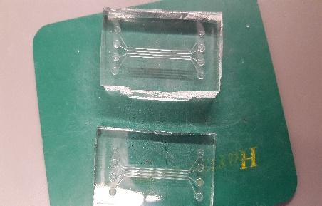
The need for large-scale analysis of cancer cells and the chemicals they release is imperative for understanding the way in which they propagate. Usually, this involves microfluidic technology and lab-on-a-chip to maximize analysis throughput with polydimethylsiloxane (PDMS). Standard microfluidic device manufacturing methods using PDMS utilize soft lithography, but they require a cleanroom and special equipment. This project focused on determining how MakerSpaces can allow microfluidic devices to be prototyped and tested using simpler, cheaper, and less time-consuming methods than soft lithography, such as laser etching of acrylic and male-female molding. Following many failed attempts, a microfluidic device was successfully prototyped after experimenting with multiple iterations of molding methods and chemical combinations for an optimal technique.
Figure: Microfluidic device manufacturing
Lesson Plan
Title: Microfluidic device prototyping
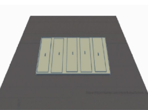
Students will examine the topics of power and speed of laser cutting. In our own summer RET experience, we inquired why the MakerSpace procedures set certain power and speed of the laser cutter and how that limits achievable outcomes. In this way, students will systematically explore how MakerSpace can facilitate low-cost prototyping of microfluidic device prototyping.
Figure: Designing microfluidic devices
Project 2: Measuring Mechanical Force exerted by Cells
Teachers: Sherlyne Gilles, Mentor: Dr. Weiqiang Chen, Research Collaborator: Levan Asatiani, Apratim Bajmai, and Kevin Guan
Research
Title: Measuring Mechanical Force exerted by Cells
This effort focused on creating a fabrication process for polydimethylsiloxane stamp (PDMS) and a prototype for the microfabricated post-array detectors (MPADS) using a microfabrication technique. The PDMS can be used as a single cell capture device and the MPADS as cellular force measurement sensors. The teacher constructed the PDM molds to visualize the cells and to be later used as MPADS. After photographing the cells, she used a MATLAB software package to analyze the traction forces exerted by the cells. She also investigated how each post can be readjusted in the center of the new grid, correcting distortions caused by cells. She formulated this research based on the hypothesis that the force can be measured indirectly by equating it to the deflection of the micro-posts using the beam bending theory. In collaboration with her partner graduate student, she calculated force from displacement of the tip of the posts on the MPAD using spring theory concept and force proportionality relationship.
Figure: MPADS force measurement
Lesson Plan
Title: Filtering Frequencies of light in MATLAB
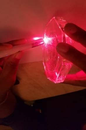
In this activity, students construct a simple conductivity probe and then integrate the probe into two different circuits to test the behavior of the probe in solutions of varying conductivity. The focus is to introduce students to the construction of a conductivity probe and expose them to several different ways of integrating the probe to obtain qualitative and quantitative measurements.
Figure: Filtering frequencies of light
Project 3: Fish-bots to Conduct Controlled Experiments on Fish Behavior
Teachers: Deborah Kalloo and Christopher Lynch, Mentor: Dr. Maurizio Porfiri, Research Collaborator: Roni Barak Ventura
Research
Title: Fish-bots to Conduct Controlled Experiments on Fish Behavior
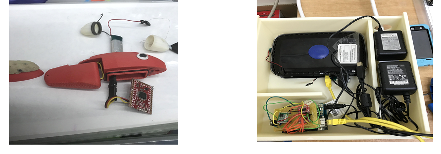
Ms. Kalloo and Mr. Lynch worked as a team to design and build a wirelessly controlled robotic-fish for use in studies of fish/marine environments, and to inspire K-12 students to study robotics. Their system contained a smartphone application to control the movement of the fish, a router that facilitated wireless communication, an Arduino Uno with an Ethernet shield, and an RF communication system. They connected a radio transmitter to the Arduino to send signals to a radio receiver inside the robotic fish. They developed and implemented a software package containing the Arduino code for radio communication with the robot and Wi-Fi communication with the smartphone. The current version of the Fish App was developed for iPhone.
Figure: Hardware for the experiment
Lesson Plan
Title: Studying Evolutionary Development of Fish using Fishbots
This lesson is directly linked to research on robotic fish. The aim of the lesson is for students to explore the evolutionary development of fish (for example sharks) and the features that contribute to this evolutionary development. Students will print different 3D models of shark’s fin tails and noses at different stages of their evolutionary development and use these to insert onto the attachable parts of a fish-bot. This will be used to compare the speeds using a distance-time graph of each shark at their evolutionary stage and by analyzing these results.
Figure: Hardware for the lesson
Project 4: Localizing multi-robot systems
Teachers: David Mensah and Mikal Moore, Mentor: Dr. Vikram Kapila, Research Collaborator: Saiprasanth Krishnamoorthy
Research
Title: Localizing multi-robot systems
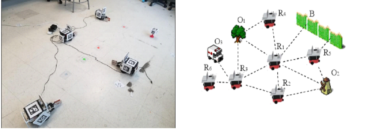
Mr. Mensah and Mr. Moore collaborated on the development of a software package based on the Robot Operating System (ROS) to facilitate seamless communication and transfer of location information between robots. To effectively setup a distributed network and enable information transfer between the robots, they had to understand the concept of custom messages in ROS. Later, using fiducial marker-based tracking, they extracted localization information and constructed a custom message that is transferred to peer robots. The project further involved reflecting the localization information of the robots into an iPad app for user interaction.
Figure: Localizing multi-robot systems and forward kinematics
Lesson Plan
Title:Using Microcontrollers to Solve real-world Problems
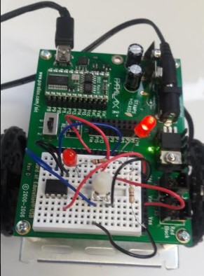
Students construct an experimental unit using a temperature sensor, LEDs, and Arduino microcontroller. They write Arduino program to instruct the LEDs to turn on as the sensor detects a certain temperature range (code basics are provided to them but the students must determine the appropriate range given their setting). When that range is exceeded, the LEDs turn off. In this way, the principle of homeostasis is demonstrated. Students then write a summary paragraph relating the sensor unit to homeostasis.Students will complete all the experiments and activities from the “What’s a Microcontroller” and “Basic Analog and Digital” kits that were used in the summer RET project. Students will apply their knowledge to solve real life application of accelerometer sensor to further understand the topics such as trigonometry and trigonometric ratios. Finally, students will select one or a combination of learned experiments and apply them to create a product or prototype that would solve a specific problem in their community.
Figure: Learning with microcontrollers
Project 5: Game-based Tele-rehabilitative Solutions for Stroke Patients
Teachers: Andrew Rose, Mentor: Dr. Vikram Kapila, Research Collaborator: Ashwin Raj Kumar
Research
Title:Game-based Tele-rehabilitative Solutions for Stroke Patients
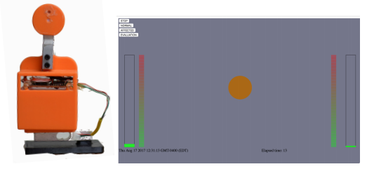
The goal of this project was to iterate through the design cycle, focusing on both hardware and software, to create better solutions for healthcare. Mr. Rose researched hardware components to measure some form/function of the body requiring training. Moreover, he investigated software components to enable interactive visualization of real-time data of body form/function, much like a video game for encouraging users to make progress in their training. After conducting research on conditions, such as heart disease and stroke, and examining the treatments, i.e. exercises, he picked one measurement that can be used to assess the patient’s progress with an exercise and determine which sensor(s) could appropriately measure it. Next, he developed a hardware prototype and addressed data visualization using software of participants’ choice (Processing, Unity, etc.), and integrated the entire solution with a gaming environment.
Figure: Game-based rehabilitation solution
Lesson Plan
Title: Physical Computation Therapy
In this lesson, students will select a condition such as heart disease, stroke, etc., and examine the treatments, i.e., exercises, that exist for it. Then they will choose at least one measurement that can be used to assess the patient’s progress with an exercise and determine which sensor(s) can appropriately measure it. Once a hardware prototype is developed, students will visualize the data using a software of their choice (Processing, Unity, etc.).
Figure: Physical computation therapy
Project 6: Constructing an Actuated Passive Walker
Teachers: Debra Rust, Mentor: Dr. Joo H Kim, Research Collaborator: Carlos Gonzalez and William Peng
Research
Title: Constructing an Actuated Passive Walker
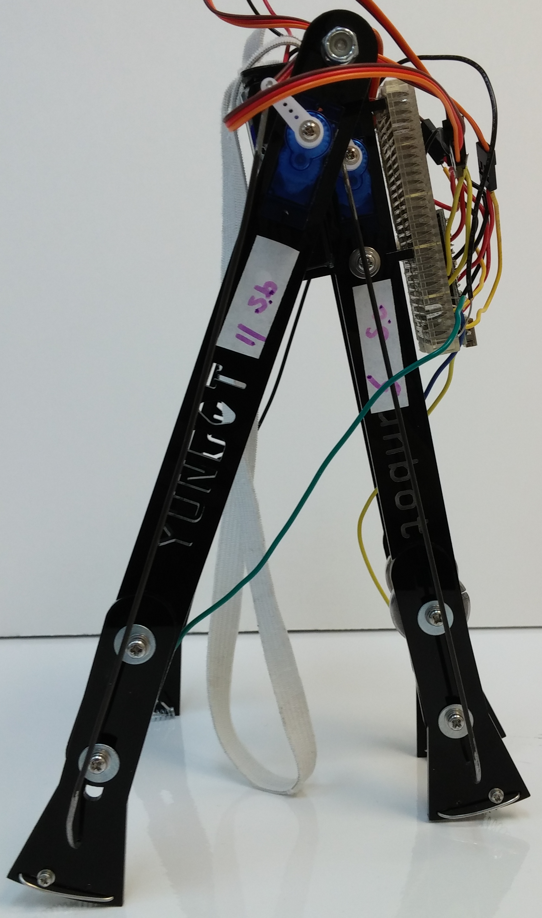
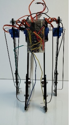
Locating the region of balance stability is a major concern in studying the dynamics of different bipedal robots. One type of a bipedal robots is a passive walker that relies on changes in gravitational potential energy to propel itself in a dynamically balanced gait, a continuous state of falling, catching, and then righting itself. Unlike other bipedal robots, passive walkers are the most accessible for studying the complexities of the gait cycle, as they exhibit both under-actuated degrees of freedom and dynamic stability with the simplest possible design. In this study, based on an open-source actuated passive walker, Rando, and using open source hardware and software, Ms. Rust created an actuated passive walker. She carefully analyzed and constructed the robot after making multiple design improvements to yield a lightweight frame with even weight distribution.
Figure: An actuated passive walker
Lesson Plan
Title: Constructing an Actuated-passive Walker
In this lesson, students will be presented with a semester-long “Maker challenge” asking them to design and engineer a walking robot. They will work in groups to provide drawings and descriptions of their designs and explore possible refinements based on scientific concepts, group discussion, and teacher input.
Figure: Constructing a passive walker
Project 7: Vertically Driven Inverted Pendulum
Teachers: Dr. Gregor Winkel, Mentor: Dr. Joo H Kim, Research Collaborator: Carlos Gonzalez and William Peng
Research
Title: Vertically Driven Inverted Pendulum
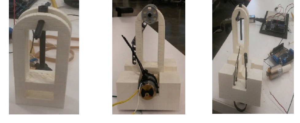
To better understand, simulate, and optimize the walking of a biped robot, Dr. Winkel modeled and constructed an inverted pendulum. By studying the inverted pendulum in an unstable equilibrium (upright position), he investigated methods of stabilizing the pendulum. He built a 3D-printed inverted double-pendulum (see Figure 3) and connected it to an electric motor. He actuated the pendulum at frequencies higher than its natural frequency to achieve and demonstrate stability in an upright position. He examined data based on Mathieu’s equation and concluded that the stability of the designed pendulum was reasonably close to theoretically predicted data.
Figure: Vertically driven inverted pendulum
Lesson Plan
Title: Building a 3 x 3 x 3 LED cube operated by an Arduino
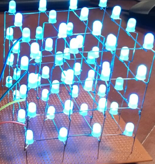
An LED cube is an interesting way to introduce high school students to Arduino programming since it uses blinking LED’s that are appealing to students. Moreover, soldering the LEDs together provides a practical experience with electronics to students. LED cubes of large sizes are becoming increasingly popular. At tech fares they are often used to present 3D video animations or light pattern formations. To build the LED cube, we will use a card board template and press holes into them to have a template to build the three layers. The positive poles of the cube are all connected. The same for the negative poles of the LEDs. The cube will be connected to the Arduino via a transistor to act as an electronic switch. Each layer will be connected to its assigned Arduino digital pin. Each column will also be connected to its assigned Arduino digital pin. The program will be simple by setting certain Arduino digital pins to high and low, the LEDS will be turned on and off. Starting with novice, long, and complex programs, students will eventually learn more efficient programming methods.
