2011 SMARTER Program Project Archive
Project 1: Analysis of Soft Materials Using Microindentation and Nanoindentation
Seth Guiñals-Kupperman and Mingyu Li
|Presentation Slides | Lesson Plan | Poster |
Research
Title:Analysis of Soft Materials Using Microindentation and Nanoindentation
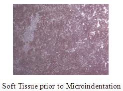
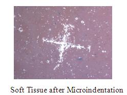
Although biological materials do not always display linear behavior, they are commonly characterized by material properties such as hardness and elastic modulus. A simplified approach will be useful in clinical routines, since analysis of the properties of soft materials such as arteries and tissues can lead to better methods of detection and treatment of disease. Elements of this approach are already employed in arterial elastography and antrhoscopy indentation testing. In this effort, a method is proposed to measure the response of soft materials to microindentation. The feasibility of such a method was tested on soft material whose properties mimic those of soft tissue, particularly arterial. The response of the material was characterized using digital image analysis and observed behavior was validated by comparison with results from nanoindentation tests.
Lesson Plan
Title: The Young’s Modulus of Jell-O®
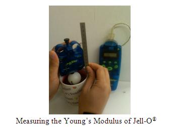
Hooke’s law describes the elastic relationship between applied loading force and the resulting stretch of elastic materials. A common subject in a first-year college physics class, one drawback to the study of Hooke’s law using springs is that students often get the impression that this pervasive natural pattern only applies to springs. The proposed lab activity attempts to show students that Hooke’s law predicts behavior in unexpected samples: Jell-O brand gelatin. Necessary for this experiment is a familiarity with using probeware, as the applied force is measured with a sensor. In addition, using a large flat object of easily measurable area (e.g. small petri dish or plastic bottle cap) allows the applied force to not pierce the sample. A glass beaker is a helpful (and generally abundant) container in which to prepare the gelatin, as its transparent walls permit visualization of the experiment. Students can use ordinary metric rulers to measure the depth to which the force probe sinks into the gelatin. Analysis of the collected data depends on the comfort level of the class and students. Novices may prefer merely graph force vs displacement. More advanced students can calculate stress and strain and graph them to obtain Young’s modulus.
Project 2: The Effect of Fiber Orientation on the Mechanical Properties of Epoxy-based Fiberglass Composites
Mangapathi Rao Donthini and Rebecca Cruz
|Presentation Slides | Lesson Plan | Poster |
Research
Title: The Effect of Fiber Orientation on the Mechanical Properties of Epoxy-based Fiberglass Composites
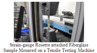
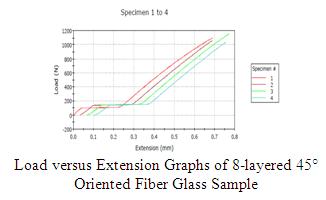
In this study, the effect of fiber orientation on the elastic modulus and Poisson’s ratio of layered fiberglass composite materials is investigated. Three different fiberglass composite samples are fabricated using epoxy resin and eight layers of fiberglass fabric oriented in three different orientations. Tension tests are performed on each sample using strain-gauge rosette, corresponding Young’s modulus and Poisson’s ratio are calculated, and changes in these mechanical properties are observed and analyzed vis-à-vis varying fiber orientation. The Young’s modulus is calculated from the slope of linear region in stress versus strain plots. The Poisson’s ratio is calculated using the dimensions of the samples and the reading of the voltages from the tension test. A systematic variation in the Young’s modulus and the Poisson’s ratio is observed with a change in the orientation of fiber. As the orientation angle increases from 0° to 45°, Young’s modulus increases and the Poisson’s ratio decreases. The volume percentages of both resin and fiberglass present in each sample are found by burning the samples and recovering the fiberglass. The theoretical elastic modulus value is calculated using the rule of mixtures. The Young’s modulus values of the samples are determined to be within the range of the theoretical values. An optical fiber sensor is used in the next step to determine the material properties of the composites. Flexural test is performed on all samples using a 1310nm laser optical fiber loop sensor. Calibration studies are conducted on the fabricated composites and the applicability of such sensors in force and displacement measurement is studied.
Lesson Plan
Title: Centripetal Force
According to Newton’s first law, an object in motion continues to move with a constant velocity in the same direction unless acted upon by an external force. However, upon the influence of a constant pulling force from a fixed point, the same object will undergo circular motion at a constant speed. Such an external force which forces the object to remain in a circular orbit is known as the centripetal force. The centre seeking centripetal force experienced by a revolving object depends upon its mass, the radius of the circular orbit, and the speed of revolution. Students will calculate the speed of the object using a Basic Stamp 2 microcontroller and a sensor set-up. After the completion of the lesson, students will be able to: (a) distinguish between speed and velocity; (b) differentiate between linear and circular motion; (c) relate Newton’s second law to centripetal force; (d) calculate the centripetal force acting on the object; (e) identify a dc motor, a Basic Stamp 2, and an experimental sensor setup; and (f) understand the working of Basic Stamp 2 and the sensor setup.
Project 3: Development and Testing of a Permeameter to Simulate Fluid Seepage within Soil Specimens
Ryan Cain and Russ Holstein
|Presentation Slides | Lesson Plan | Poster |
Research
Title: Development and Testing of a Permeameter to Simulate Fluid Seepage within Soil Specimens
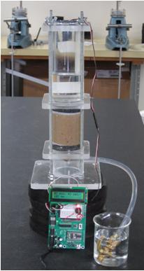
This research explored the characteristics and properties of assorted soil samples by running falling head tests in a permeability chamber. Permeability is the ease with which water can flow through a soil volume. Permeability is extremely important because it controls the strength and behavior of soils. It is of major concern in the design and construction of buildings and/or underground structures where groundwater needs to be contained or evacuated. Particular attention was paid to the utilization of transparent soil mixtures of aquabeads and fused quartz as they allow for a greater visualization of the particle behaviors in addition to flow visualization. A permeameter was first designed in Google SketchUp and then machined of cast acrylic tubes and sheets that were compressed with the addition of threaded rods. The Parallax Basic Stamp 2 microcontroller was utilized to measure the rate of falling head and derive the rate of flow for different soil specimens. The chamber design was based upon a factory constructed permeameter from the ELE Corporation.
Lesson Plan
Title:Mechatronic Clinometer
Students will learn how to measure the height of an object by using a mechatronic clinometer. This lesson will introduce to students the basic concepts of trigonometry and proportions which will be illustrated through real-world robotics hardware and software to demonstrate to students the interplay between science and engineering. Students will explore the question, “how does a smart phone know to rotate from portrait to landscape orientation when a user rotates the phone?” Accelerometers and ultrasonic sensors will be investigated. Demonstrations will provide evidence as to how accelerometers can measure gravitational direction. This principal will be shown with a plumb line attached to a protractor. Students will use graph paper to make scale drawings to solve for unknown heights. Once students have become familiar with the simple clinometer they will employ the mechatronic clinometer. Students will discuss the advantages of automation and where it can best be put in to real world applications.
Project 4: iPhone-Controlled Robotic Projects
Jeffrey S. Bernhardt, Hilary Mallar, and Lindrick Outerbridge
|Presentation Slides | Lesson Plan | Poster |
Research
Title: iPhone-Controlled Robotic Projects
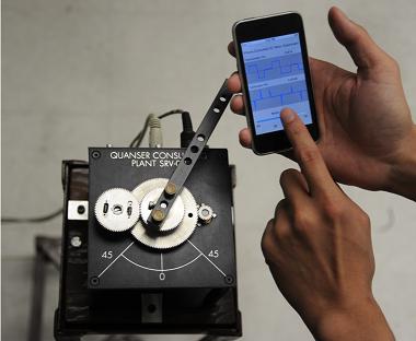
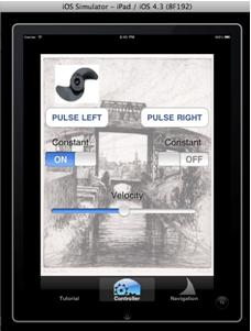
This effort focused on exploring a series of mechatronic projects that can be remotely monitored and controlled using the iPod or iPhone mobile devices. Our hardware platform involved Arduino microcontroller interfaced with Wi-Fly shields, a variety of laboratory testbeds integrated with the Ardunios, and iPods or iPhones with embedded sensors, e.g., accelerometer, touch, buttons, etc. Our software environment consisted of C-like programs for Ardunio, Objective C for iPods, and Core Graphics Framework for iPod graphical user, interface, animation, etc. Specifically, our effort resulted in the development of an integrated hardware-software platform wherein: (1) a user interacts with a custom created graphical user interface on a mobile device to send TCP/IP control commands to a mechatronics/robotics device over a Wi-Fi network; (2) an Arduino with a Wi-Fly shield receives the remote user’s control commands over the Wi-Fi network; (3) the Arduino serially communicates the control commands to the mechatronics/robotics device, receives sensory data from the mechatronics/robotics device, and communicates the received sensory data back to the mobile device over the Wi-Fi network; and (4) the mobile device app stores, displays, and plots the received sensory data, which can be analyzed in real-time and used to make new command decisions. For our mechatronic projects that currently use MATLAB to interface with the Arduino, in near future, we expect to eliminate the use of MATLAB and interface to these mechatronic projects directly from the Arduino with Wi-Fly shield. Moreover, we plan on advancing the iPhone applications so that they facilitate interaction between the virtual and physical worlds, i.e., a user controlled robot animation causes a robot in the physical world to behave as the robot in the animated world. This research involved all principles of robotic systems, including mechanical and electrical subsystem design, hardware interfacing, and programming.
Lesson Plan
Title: a-MAZE-ing Robotics
This lesson will expose students to the concepts of using sensor information to control robots. Students will work as a team to build a robot to navigate a maze efficiently. They will learn the science and principles of how sensors work, how to design algorithms, and apply their problem solving and logic skills to programming. After this lesson, students will be able to: (1) build a robot to navigate through a maze; (2) explain the advantages and limitations of different types of sensors (e.g. touch, rotation, ultrasonic, and light); and (3) program a robot’s movement based on sensor information.
Project 5:i-Device Controlled Robotic Buoy with Capabilities to Collect Environmental Data from a Body of Water
Noam Pillischer
|Presentation Slides | Lesson Plan | Poster|
Research
Title: i-Device Controlled Robotic Buoy with Capabilities to Collect Environmental Data from a Body of Water
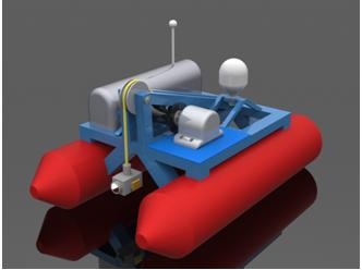
The Gowanus Canal, a body of water located in Brooklyn, is considered one of the dirtiest bodies of water in New York State. The goal of this project was to build a robotic buoy that can collect data using sensors and send that data to an i-device. The i-device can also command the location of the robot in the canal. The intended audience for this robot is the general public, who can learn about the environment through interacting with the robot. This project involved building a robot-frame that can float and move in the water as well as carry the devices used to sense and collect environmental data on the body of water. A microcontroller was programmed to listen for commands from the i-device and send environmental data to the i-device on a wireless network. An Arduino UNO was used as the microcontroller along with the Arduino motor and wifly shields. A graphic user interface was developed for the i-device to send commands and display environmental data from the robotic buoy’s sensors. Objective C and x-code nib files were used for developing the graphic user interface.
Lesson Plan
Title: Using an NXT Robot to Learn about Programming and Newtonian Mechanics
Students will learn about vectors, velocity, and acceleration through physics modeling and using the NXT robot. Working in teams of three they will mark the distance that the NXT robot travels. After data collection, they will represent the distance versus time relationship using different types of models. Through further exploration they will develop the relationships between acceleration, velocity, displacement, and time. All activities will involve the NXT robot but with each activity the robot will be moving at different rates. The culminating activity and lab assessment will involve the students programming the NXT robot so that its velocity matches a specified velocity vs. time profile. To differentiate between beginner versus advance students, NXT MINDSTORMS and Robot C programming environments will be exploited. Finally, advance students will be challenged to program their robots to move according to a specified acceleration versus time profile.
