|
|
||||||||||||||
|
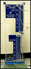
The laboratory liquid level control system consists of two tanks with orifices and level sensors at the bottom of each tank, a pump, and a water basin (basin not shown in VRML diagram). The two tanks have same diameters and can be fitted with different diameter outflow orifices. In this laboratory setup, the pump provides infeed to Tank 1 and the outflow of Tank 1 becomes infeed to Tank 2. The outflow of Tank 2 is emptied into the water basin. In this exercise, students model, calibrate, and control the two-tank liquid level system. In particular, this experiment exposes students to the fundamental modeling principle of fluid mass balance, pressure sensor calibration, and a feedback control design methodology for a state-coupled, two-tank liquid level system. Proportional-plus-integral controllers are used for Tank 1 and Tank 2 in this experiment. The water level in Tank 2 is controlled by controlling the outflow through Tank 1. Four knobs, providing adjustability of the control gains for both tanks, are provided in the Control and Animation panel. You can select the desired Tank 2 water level by moving the slider labeled reference command. The plot given in the control panel provides the Tank 2 water level response. For additional details on the algorithmic implementation of this controller see the Real-Time Control Laboratory Manual - Experiment 6.
To view a sample movie of the Two Tank experiment, click on the following link:
|
||||||||||||||
|
|
Click
on the following image to load the two tank experiment.
|
|
|
|
|
