This experiment is currently disabled.

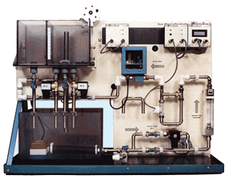
In this experiment, students learn to apply control design techniques on a liquid level process system to control the liquid level in a holding tank. This liquid level process system consists of a reservoir (as seen in the lower left hand corner of the below figure), a holding tank (directly above the reservoir), a piping channel (middle to lower right hand side of below figure), a fixed voltage water pump (not seen in figure), and a servo valve (center of below figure).

In operation, the liquid level process system pumps liquid from the reservoir into a piping channel . In an intermediate location along this piping channel, liquid passes through a servo valve, which controls the flow rate pumping into a holding tank. In addition, liquid exits the holding tank by means of a constant diameter exiting orifice (located at the bottom of the holding tank) .

The objective of this experiment is to design a proportional-plus-integral controller that makes the liquid level in the holding tank track a desired setpoint level.

You can change the viewpoint for the animation window as follows. First, place the mouse cursor in the animation window. Next, click the left mouse button and drag the mouse to get the viewpoint you prefer. You can also resize the object being animated by pressing the "Alt" button on your keyboard, placing the mouse cursor in the animation window, clicking the left mouse button, and dragging the mouse.

To view a sample movie of the Level Control experiment, click on the following link:

LevelCont.mpg
File Size: 8.5M
Download Time: 45 seconds for a T1 connection
This experiment is currently disabled.
Home - Info - Downloads - Experiments - Credits - Links - Contact