Applied Dynamics Lab
Prasad Akavoor and Yancey Quiñones
Energy Consumption Rate in a Robot/Motor
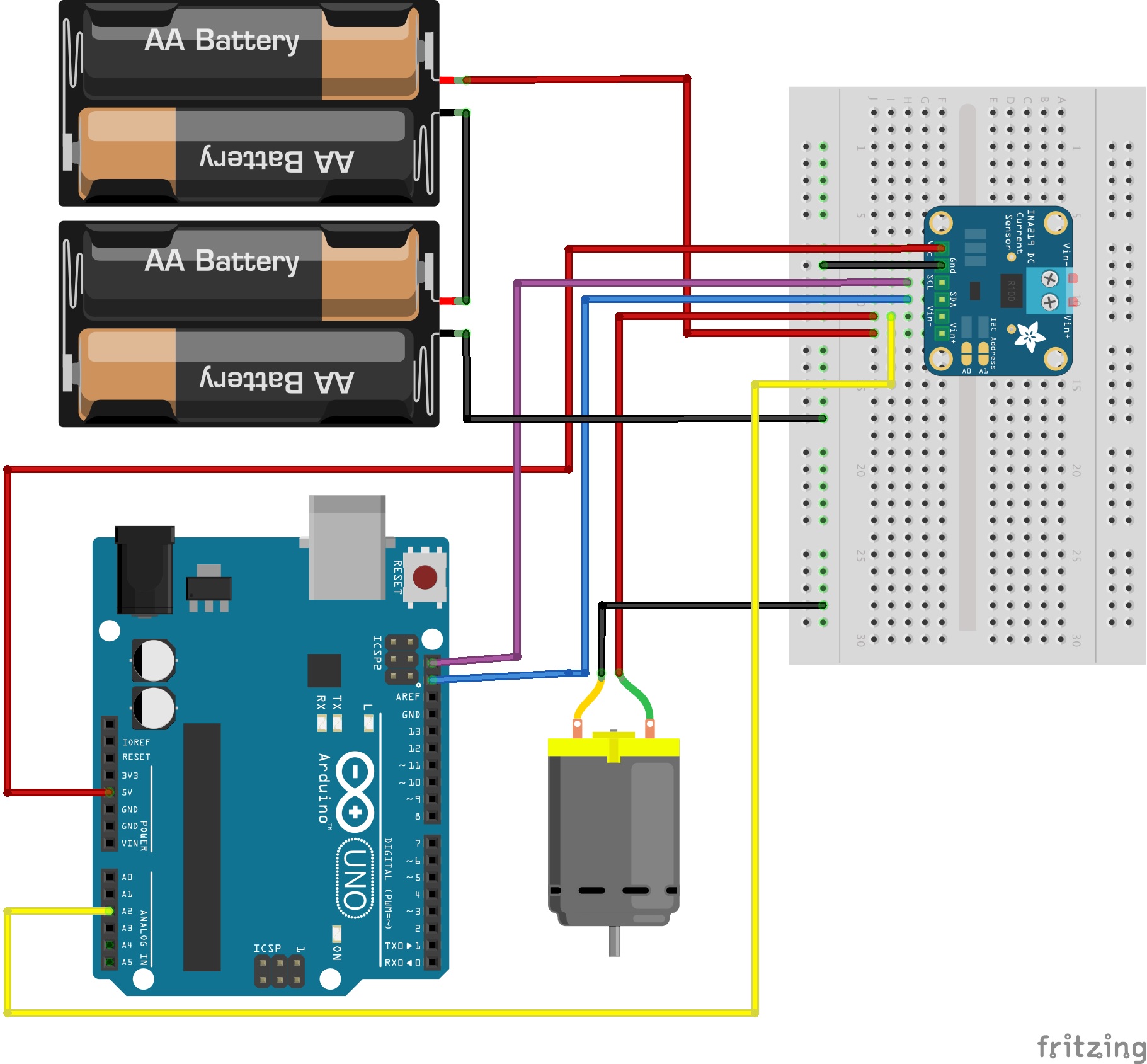
We decided to continue running the motor without the motor shield, because the shield is not central to our goals. We realized that the motor must be connected to the low end of the current sensor or it won’t read voltage! Also, we discovered that the drill press that we had hoped to use to do positive and negative work on the motor would not work because it rotates more slowly than the motors we have been experimenting with. This means that we are better off just trying to apply a mechanical load by pressing, as we had been doing, an object – a cork in our case – against the spinning axle of the motor. This way we could stall the motor if we wanted to. Driving the motor in reverse essentially puts it on the low side of the current sensor, thereby rendering the voltage readings meaningless (nearly zero). We, therefore, ran the motor only in one direction. It’s important to mention a key difference between the two current sensors we have been using, INA219 (resistor based) and ACS712 (Hall effect based). The former gives us both the current and the load voltage directly while the latter gives only the current. In order to measure the load voltage we must, therefore, connect the “high end” of the motor to one of the Analog pins on the Arduino. We did this for INA219 also just to be sure that the sensor values of load voltage and direct measurements from the analog pin were comparable. And they were! At the end of the week, we finally got the voltage and current measurements to work using both types of sensors. The currents measured with the sensors were compared to those measured by a DMM, and there was good agreement between them. We wish to point out that the DMM measured about 230 mA (or, 0.230 A), whereas INA219 measured an average value slightly larger than 0.230 A and ACS712 measured an average value slightly smaller than 0.230 A. In all, we took data for following six different cases for each of the two sensors.
- Motor with no mechanical load
- Motor with a brief mechanical load, but not stalled
- Motor stalled and not recovered
- Motor stalled for 10 s or so and then recovered by unplugging and resetting
- Motor stalled for 20 s or so and then recovered by unplugging and resetting
- Motor stalled for 10 s or so and then recovered on its own
In each case, we plotted power vs. time. We note that for the ACS712 we used an op amp to amplify the output voltage and scaled it appropriately to calculate the current in the circuit.

