Dynamical Systems Lab
Horace Walcott and Brian Lam
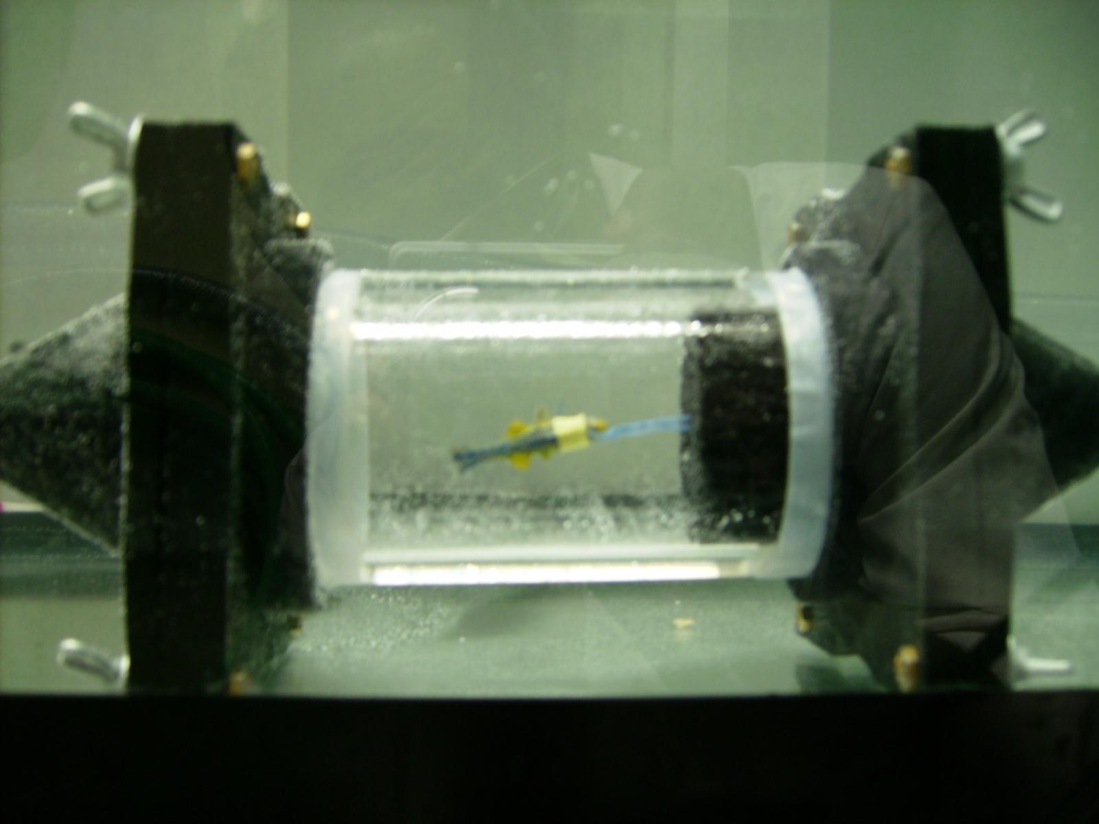
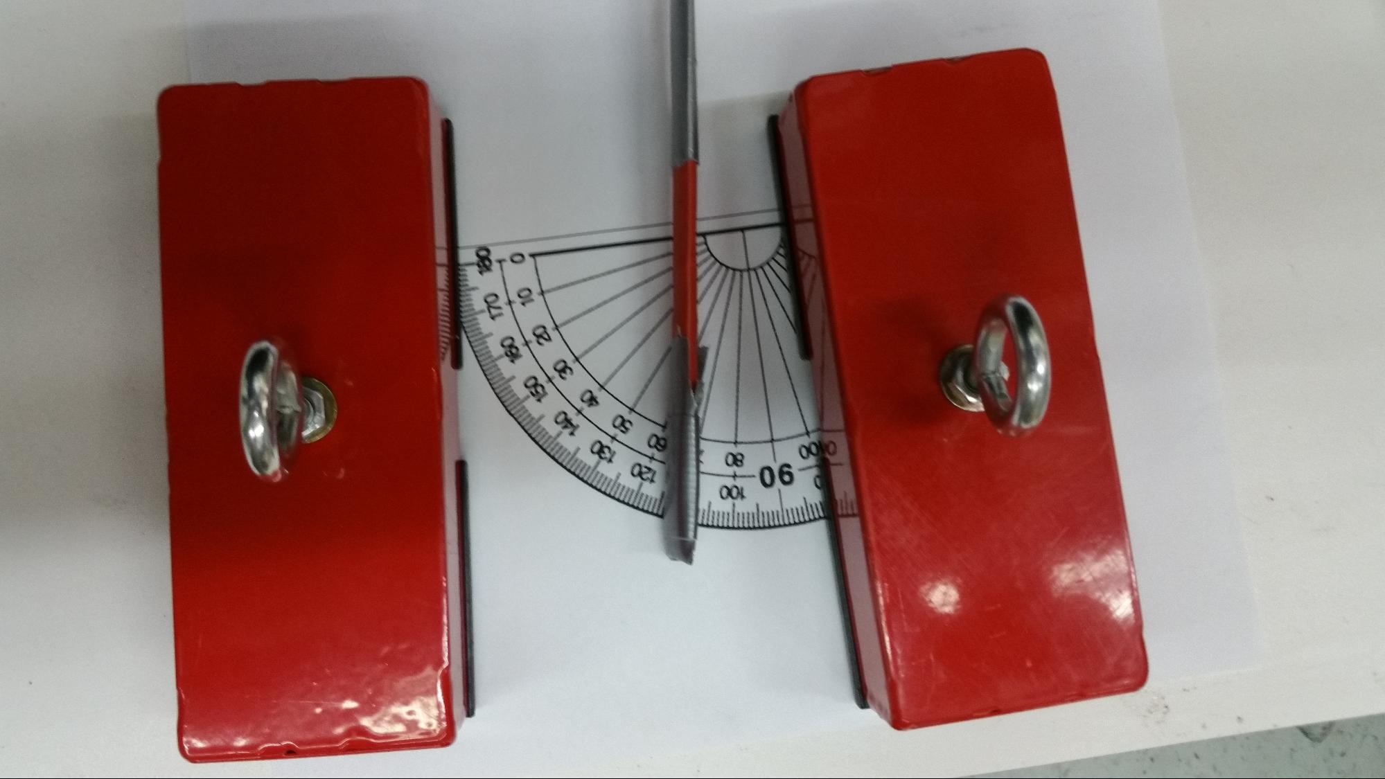
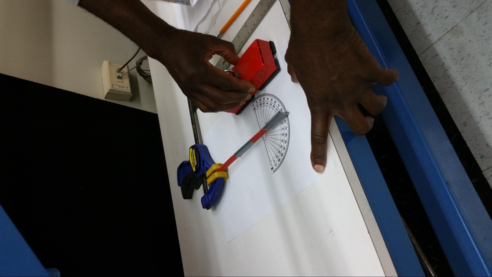
This week we met with Violet Mwaffo and the rest the team of Dr. Maurizio Porfiri’s Dynamical Systems Laboratory. For our experiment we have been planning on contributing to the design of an artificial zebrafish and enclosed flow chamber, oscillating the replica zebrafish tail in a lifelike manner, and observing the behavior of a live zebrafish in the wake of the replica. We plan to monitor water temperature and flow rate, as well as dissolved O2 and CO2 concentrations, in the wake of both the replica and the live fish, and use thermal imaging as well as a wireless electrocardiogram to monitor the biological response of the live fish. At this point in time there are two options for actuating the body and tail of the replica fish, for the generation of carangiform locomotion. Option 1 will utilize a small hole drilled into the top of the swim chamber, with a servo motor attached to a microcontroller outside the chamber rotating a thin shaft inside of a hollow tube, attached to the fish replica. Option 2 involves placing very small rare earth magnets inside the tail of the replica fish and construction of Arduino controlled electromagnets on either side of the swim tank. Both options should enable lifelike carangiform motion in the replica fish. Many resources on zebrafish physiology are available due to the use of zebrafish in genetics studies and developmental biology [1]. In recent years, zebrafish have been used more and more as laboratory animals as opposed to rodents, such as mice, due to their ease of care and ability to generate large numbers of new embryos very quickly. Zebrafish embryos are transparent, but while adults are not, much work has been done with them showing that their behavior and responses to stimuli are easily observable, as described by R. Ma in 2012 [3]. We also found research on optimal propulsion of robotic fish while still maintaining the carangiform model of motion [2]. In order to examine the possibility of controlling the fish replica using magnetic fields, Horace brought a variety of magnets from his school to use with thin plastic beams, representing slender beams. As shown in Figure 3, the magnets were able to cause bending in the beams at a distance equal to the radius of the swim chamber. Measurements were made of the linear displacement of the beam, angular displacement of the beam, shown in Figure 2, and magnetic field strength at different distances from the magnets. Magnet wire as well as iron rods will be ordered in order to construct custom electromagnets for Option 2 of the project. Together with Howard Chien, we have made many improvements to the swim chamber of the replica and live zebrafish and have discussed varying methods of preventing leaks and maintaining laminar flow in the tube. As shown in Figure 1, almost all of the air has been purged from the flow chamber by assembling it underwater, and an example replica has been attached in such a way as to maintain an upright and forward position in the chamber. Different connections and fittings will be modeled in SolidWorks to be 3D printed, or ordered online in order to prevent leaks, facilitate the measurement of water conditions, and more efficiently conduct the experiment.
References:
[1] C. Binesh, 'Elevation of temperature and crowding trigger acute viral nervous necrosis in zebra fish, Brachydanio rerio (Hamilton-Buchanan), subclinically infected with betanodavirus', J Fish Dis, vol. 37, no. 3, pp. 279-282, 2013.
[2] J. Yu, S. Wang and M. Tan, 'A simplified propulsive model of bio-mimetic robot fish and its realization', Robotica, vol. 23, no. 1, pp. 101-107, 1999.
[3] R. Ma, M. Distel, X. Deán-Ben, V. Ntziachristos and D. Razansky, 'Non-invasive whole-body imaging of adult zebrafish with optoacoustic tomography', Physics in Medicine and Biology, vol. 57, no. 22, pp. 7227-7237, 2012.


