Dynamical Systems Lab
David Arnstein and Horace Walcott
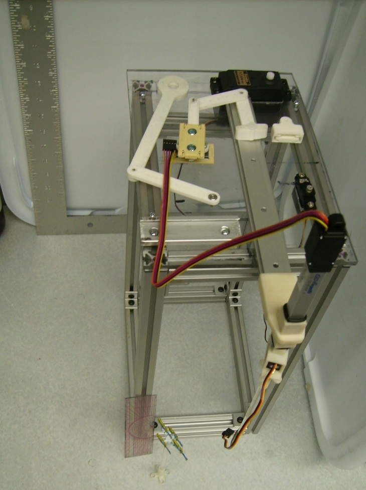
This week we assembled a new bio-mimetic platform to study fish behavior, including the abaxial appendage attached to the major horizontal arm of the device (Figures 1 and 2). Additional plastic components required for the function of the arm were 3D printed. By means of the ProAnalyst software, tracking studies were conducted for the simultaneous operation of two motors of the major arm of the platform and the operation of the four motors of the platform (Figures 3 and 4). We also conducted tracking studies on the operation of the four motors for an in-house developed code for simulating the linear darting and pelvic tail flutter or twitching motion of the zebra fish (Figures 5 and 6). A mix up in the mail room resulted in a week waiting for parts to arrive from a vendor when, in fact, the parts were sitting downstairs. Unfortunately, this lost time resulted in a compressed build schedule. We discovered interesting design problems with the existing SolidWorks platform schematics that we will not have time to correct, but will report proposed solutions in our final paper. This experience (going from design drawings/computer modeling to actual construction) illustrated important aspects of the design/modeling/buildling engineering cycle. A similar process happened with software development for the Arduino: we started getting unpredictable behavior in our program and discovered that the program code was overlapping with variable/memory space in the Arduino. This forced us to remove comments and explanatory user text and tighten up the code. It also meant that adding additional modules to mimic natural zebra fish behavior is impossible without a complete rewrite of the current code.
Figure 1. Bio-mimetic platform.
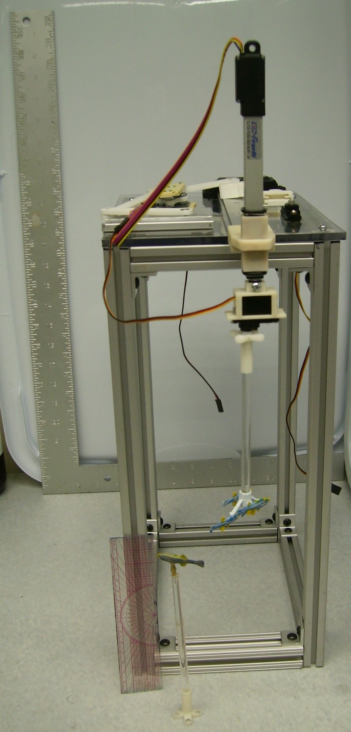
Figure 2. Biomimetic platform containing multiple fish replica on a transparent rod.
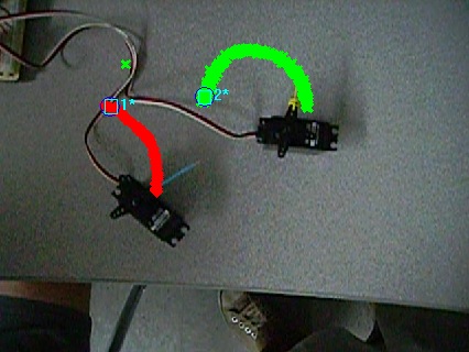
Figure 3. Path of the horns of two motors.
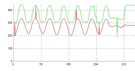
Figure 4. Displacement graph of the two motors. Y axis is the displacement.
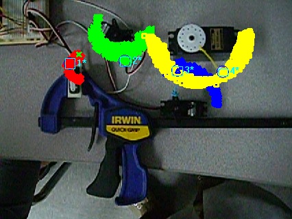
Figure 5. ProAnalyst tracking of four motors simulating the motion of killifish in the 3D spatial shapes.

