July 9, 2014, Day 12:
Ulugbek Akhmedov
Stuyvesant HS, Science Teacher since 2006
Buttons or Switches! This must be fun!
Today, we learned a great deal about buttons and switches. Some stuff was pretty straightforward. A few details follow.
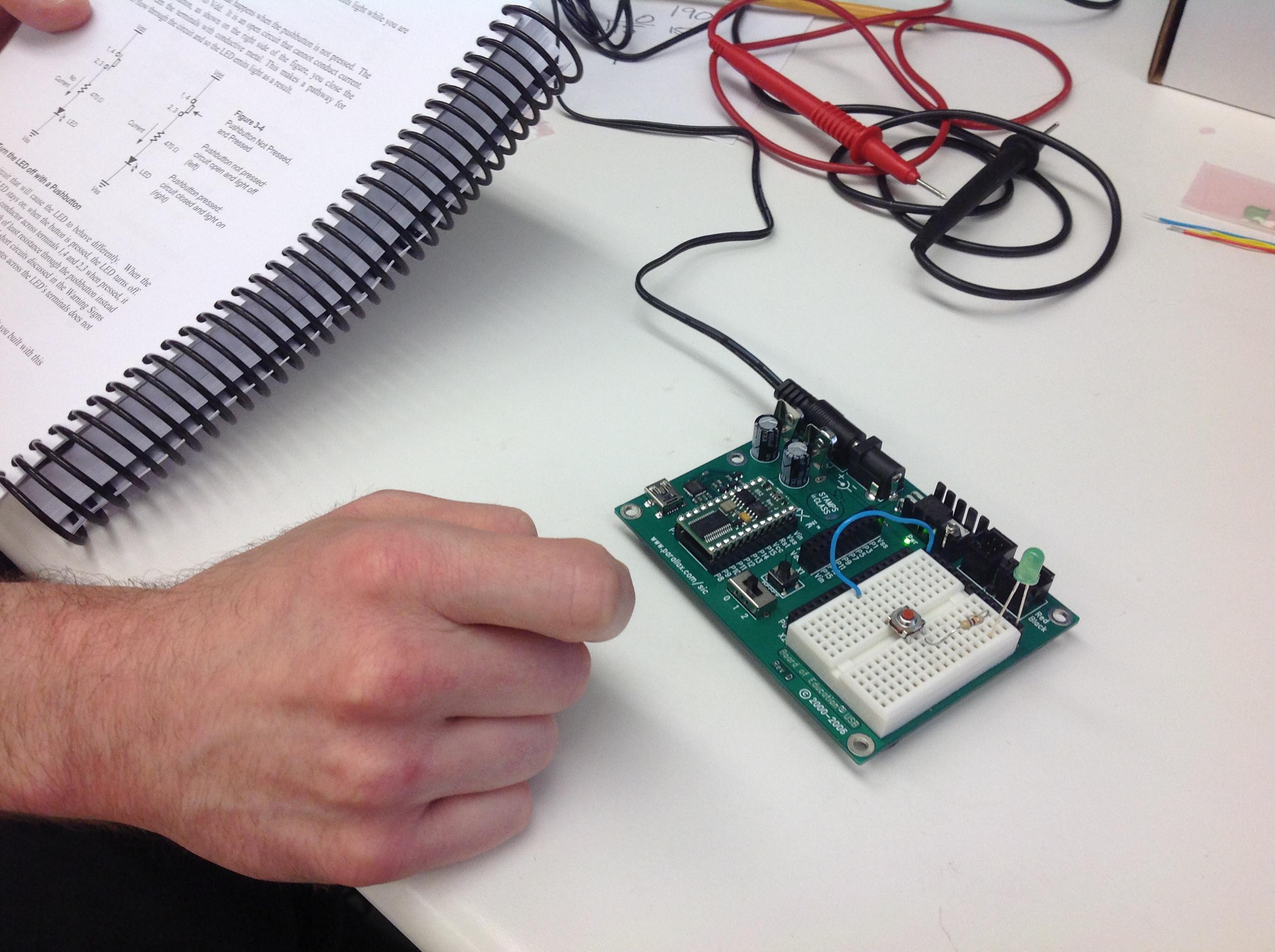
Different types of switches/buttons were used for placement on our breadboards. Four pins of the buttons allowed it to be stabilized on the breadboard. The four pins of the button are internally connected in two pairs each, so that the pins within the pair have the same potential.
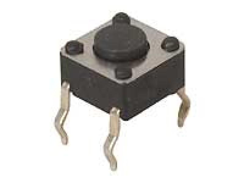
We were provided buttons that act as momentary switches that allow either temporary ON (or OFF) position under user action and when user action is removed it reverts to its default OFF (or ON) position by a spring inside the button. That is, our momentary buttons do not allow permanently switching the position - it always returns to the default position. Button can be normally closed or normally open, i.e. normally ON or normally OFF. The following is an illustration of a button we used.
Fig. 1. A simple 4-tip On/Off button or SPST switches (single pole, single throw)
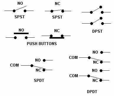
There also exist switches which can permanently change the position from one to another. A switch can be "thrown" from one position to another. It can also open and close two or more circuits simultaneously. A switch can also open one circuit in a particular position while having a different circuit closed.
Fig. 2. Schematic representation of various switches
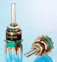
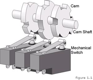
Fig. 3. On the left is rotary switch with multiple positions. On the right are Limit Switches used to automate certain mechanical steps.
Limit Switches
Limit switches can be used to limit certain action: motion, pressure, rotational motion, switching the direction etc. these can be used in robots to sense and respond to mechanical obstacles, conveyors to count, or switch On and Off for particular parts to be sorted etc.
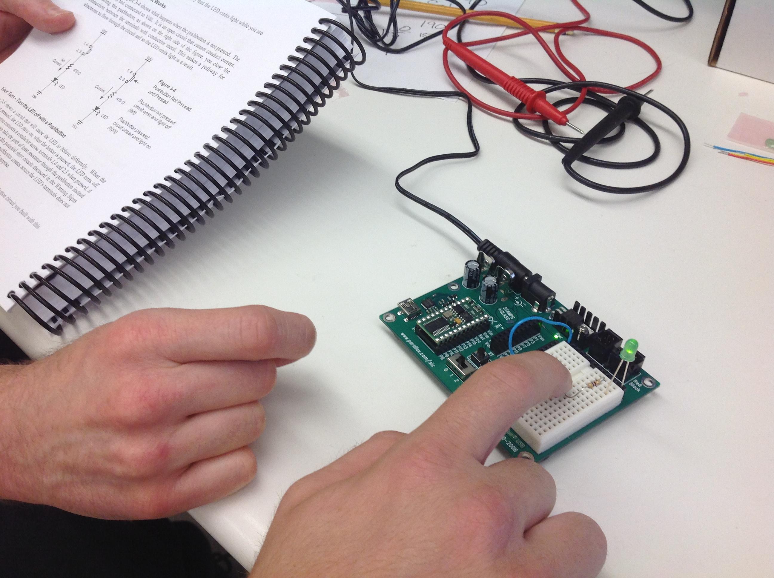
Once we got to lab we had an opportunity to build and test simple circuits with switches.
Fig. 4. Using a simple momentary button to control an LED
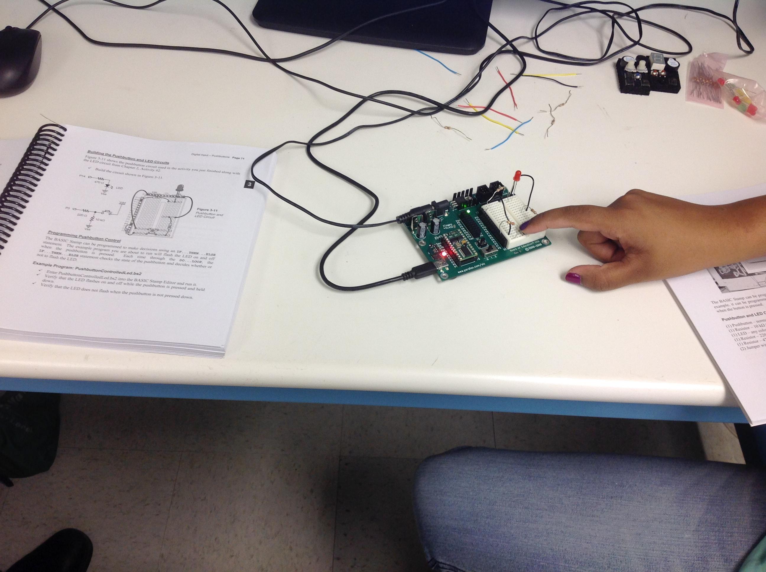
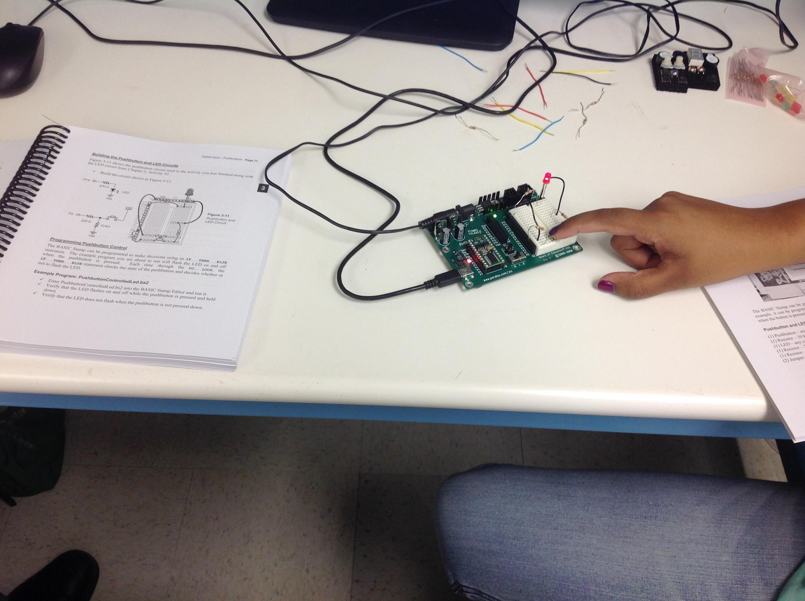
We then learned to program the microcontroller and construct circuits so that we work with a button and control its default setting to be either On or Off (i.e., active low or active high).
Fig. 5. Using the button to let LED to blink continuously.
Capacitors
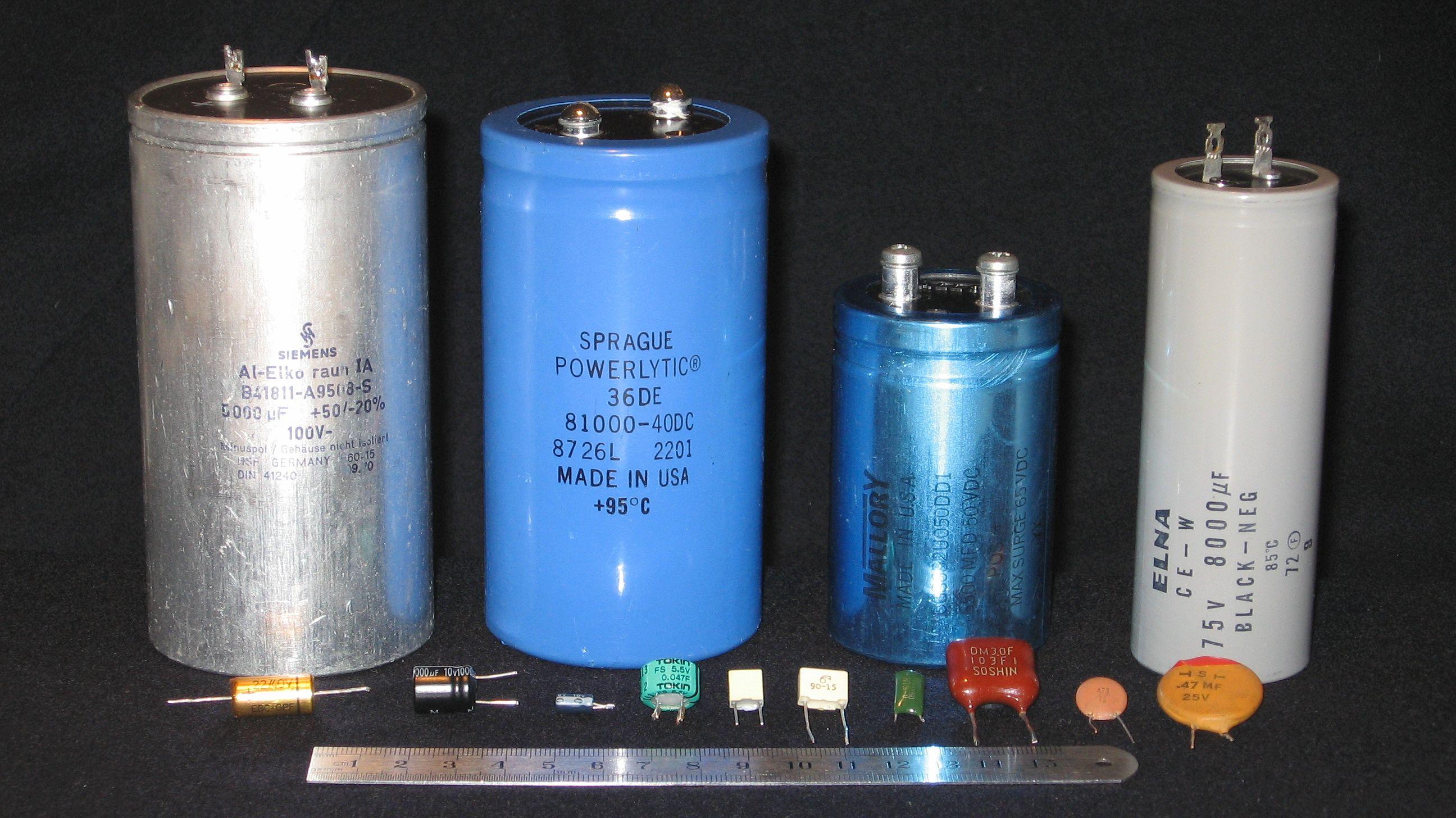
Later we used our electronic kits to charge and discharge small capacitors. Some details about capacitor are below.
Fig. 6. Various types of capacitors.
A capacitor is used to store electric energy as charge, analogous to a mechanical spring that is stretched (or compressed) by external pressure. Voltage is an electrical analogy of the mechanical pressure.
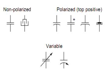
Fig. 7. Schematic representation of various capacitors: non-polar capacitors, polarized capacitors, and variable capacitors
In case of polarized capacitors it is important to connect them with proper polarity. Just like in case of LED lights, the longer "leg" should be connected to + of the Voltage source (Vdd on the electronic kit.)
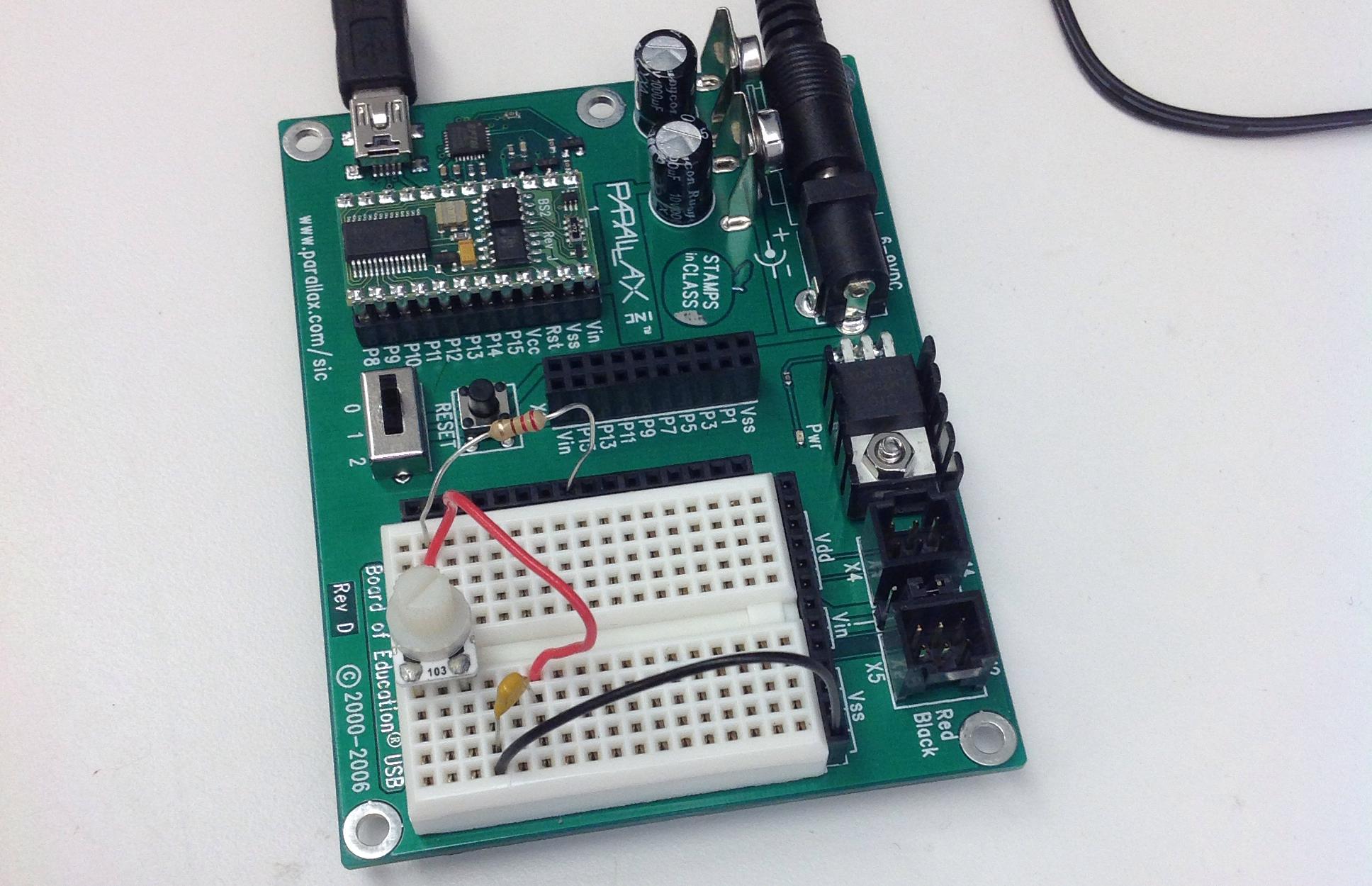
The microcontroller was next used to determine the discharge time of a capacitor. RCtime is the time it takes to charge or discharge a capacitor. It depends on the capacitance and the resistance in the circuit.
We found that for 3300 microFarad capacitor the time was 1.1 second and for 1000 microFarad, it was 0.4second. These times are lower then expected from the product of R*C. However, we knew that the program would equate any voltage below 1.3 V to zero and stop the timer.
For even smaller capacitors, it was possible to program the timer so that it would read the potential on a capacitor relative to the ground in 2 microsecond intervals. This gave us around 300 microsecond time which is inconsistent with calculations. So we should go back tomorrow and check again.
Fig. 8. Measuring the time constant of 104 capacitor (C= 10^4 pF)
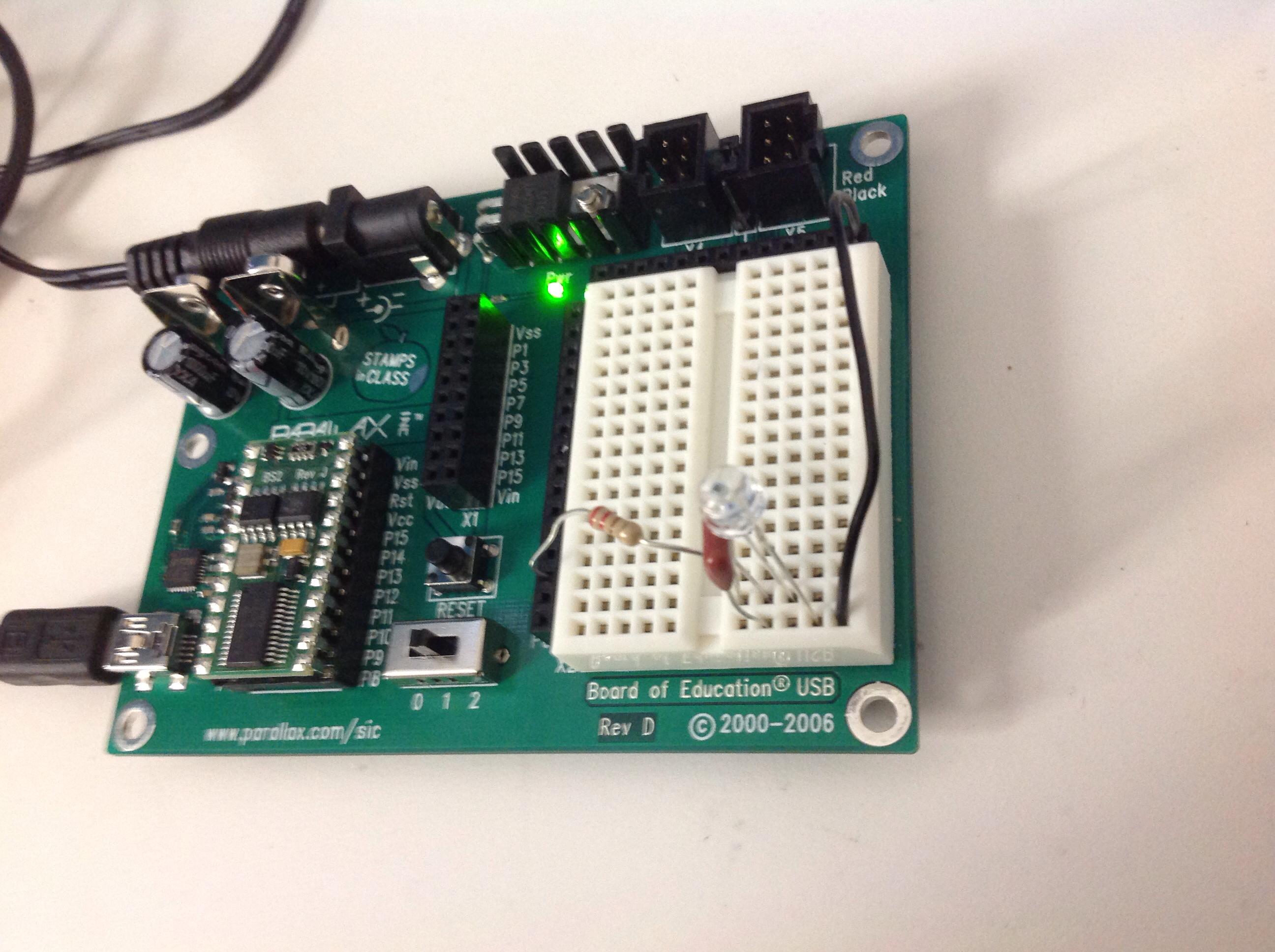
Finally, we tested the sensitivity of a phototransistor to light by varying the illumination of the filaments and reading the time the capacitor takes to discharge. The greater the illumination the shorter time it took for the capacitor to discharge. This is due to the fact that the photo-element functioned as variable resistor in RC circuit, and the variability of the resistance was dependent on the amount of light.
Fig. 9. Testing a phototransistor and a capacitor
It was a great day. It feels we are accelerating the rate of learning!
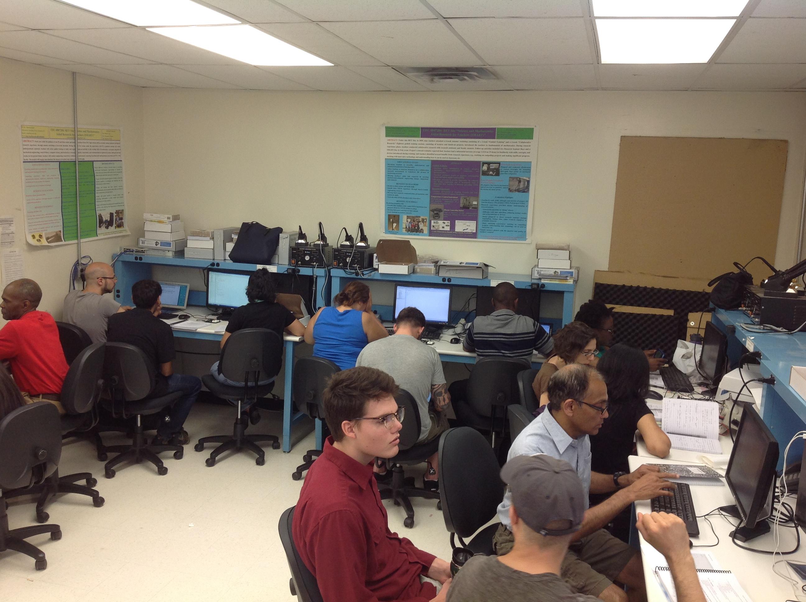
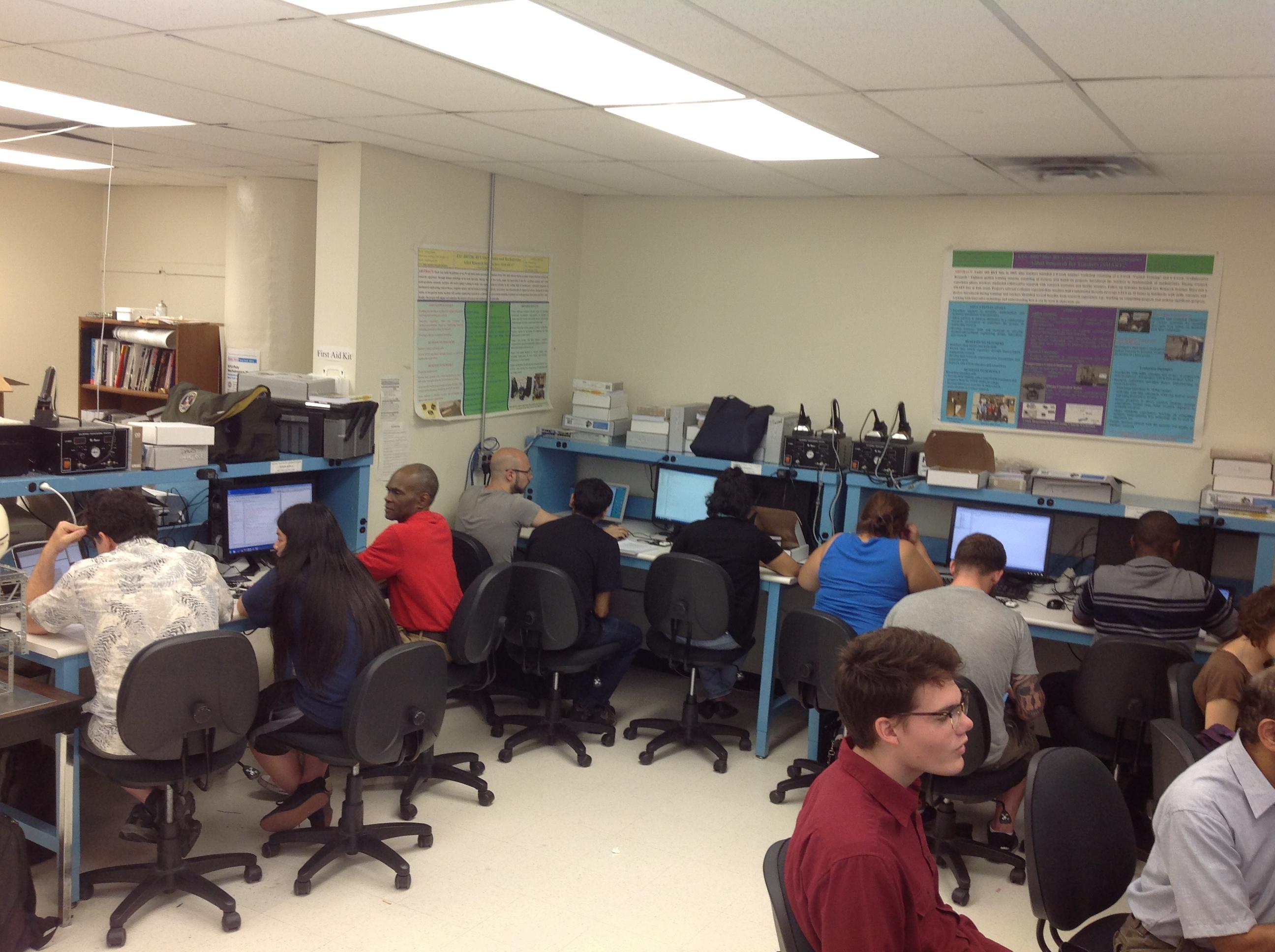
Everybody was working hard!
