July 7, 2014, Day 1:
David Arnstein
Head, Science Department—The Chapin School with 30+ years of STEM teaching and administration experience
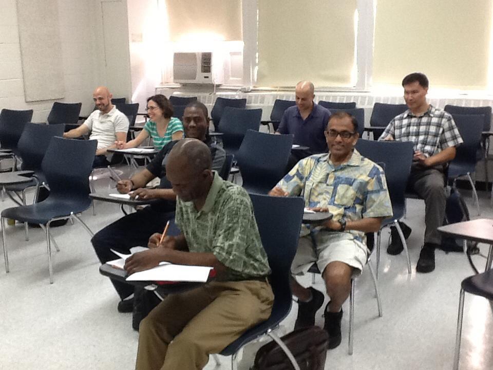
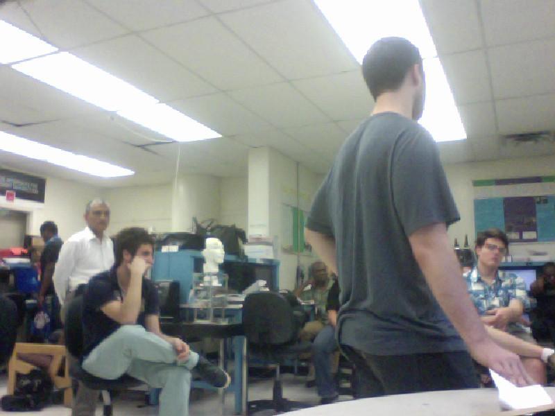
The first day was as introduction to the SMARTER program. We saw examples of projects done under the 4 week format (many focused on creating a "teaching/learning lab") and also some under the new 6 week format (projects grow out of actual engineering research). It became clear that opportunities for original and creative research are everywhere and encouraged. The cohort met the head of the mechanical engineering department who reiterated the importance of STEM education. Through one “surprise activity” we understood what we are likely to learn during the next two weeks. A second surprise was offered when we went into the lab to complete some surveys: boxes of "toys" – microcontrollers, sensors, various kits, and manuals for assembling projects.
Lunch was stupendous: 70 minutes to browse local eateries, enjoy the sunshine, and consider all the work ahead of us (research paper, powerpoint presentation, curriculum creation, weekly notes (daily for first two weeks), lab internships, and, most likely, additional expectations not yet revealed.)
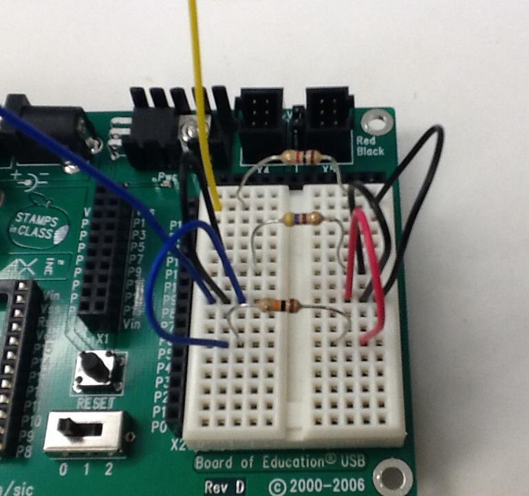
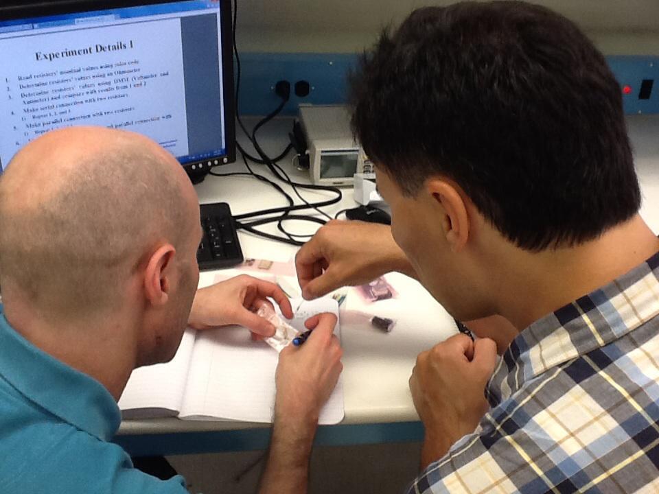
Post lunch we had a short lecture on resistors, batteries, Ohm’s law, and simple circuits. Then we went to the lab to build and test these circuits. We checked out accuracy of resistor color bands by confirming with Protek Multimeter set up as Ohmmeter. The last step was applying voltage to the board and measuring amperage and voltage throughout the circuits we built.
There were some problems with our ammeter setup so it was not possible to verify the Ohm’s law by measuring both voltage across and amperage through the resistors, but we calculated expected amperage based on measured voltage drops and known resistance. When we borrowed an ammeter from another group, it was possible to verify the Ohm’s law. All groups seemed confident in using components, multimeters, and breadboards to build simple circuits. The final circuit used a variable resistor in parallel with a second resistor to control the output voltage at two points of a circuit. By building the circuit and using a voltmeter at the output locations, it was easy to set the dial to create a desired output. Mathematically, it was difficult for some to calculate the needed resistance, and this calculation was demonstrated to the group by our instructor.
Other highlights of the day included: air conditioning being repaired/replaced made for heated and exciting research into circuits. With any luck, future experiments will be somewhat cooler. Also, we were visited by the Director of the Center for K-12 STEM Education who mentioned that there are several other programs running this summer - including students placed in research labs - and that there may be opportunities for live webcasts or other promotional activities.


