Discussion
Despite the seemingly
simplistic needs of the robot, the design and the parts require a lot more
attention. First the tank had been placed in the front to offset the weight
provided by the roller; however, this proved to be dangerous as water would be
traveling above the circuitry. Therefore, all of the circuitry was placed in
the front on two tiers: one for the breadboards and one for the
microcontroller. The tank was also connected to a solid instead of a flexible
pipe that rotates on the same center point as the roller. Unfortunately, the
roller attachment had to be slightly off-center in order to line up the roller
with the robot. This disrupted the symmetry between the two turns, requiring
different adjustments.
?Another challenge was getting
the robot to turn precisely 180 degrees and 90 degrees and go straight
afterwards. Not only were the servo motors that were being used temperamental
and refused to go straight in the first place, but also the roller attachment
ultimately dragged and forced the robot to drift to the side of the roller. Hence
an S-turn was applied to the program to straighten the roller by dragging it
further into a turn [fig.3]. However, several design flaws prevented constant
results from occurring; one was the rotating back wheel, which created
unpredictable turns; another was the offset roller position, which created
uneven drags on the two sides.
?In the future the several
design flaws discussed previously will need to be fixed in order to refine the
turning. Also, the servo motors must be replaced with dc motors because more
power may be needed to pull the roller along with the liquid. A centered roller
attachment along with the back corners cut to prevent the roller from getting
caught on the corners is necessary.
?
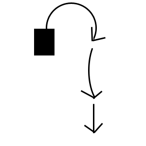
Fig.3 S-turn for 180 degrees